Knowledge Base
Working with Reality Capture Scans
A BIM model says what the building was meant to be. A scan says what it is. Reality Capture is where the two meet: attach point clouds and 360 panoramas to a facility, stand where the surveyor stood, measure inside the cloud, and compare it against the drawing.
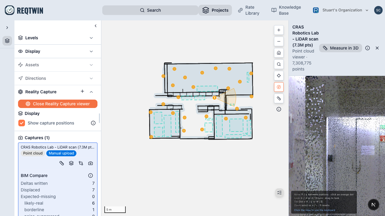
The reality capture viewer: a floorplan with orange capture-station dots and a view cone, next to a point cloud of the same space.
Finding it
Reality Capture is a section in the map's left panel, alongside Levels, Assets and Directions, collapsed by default.
Its heading carries a coverage percentage: how much of the building sits within reach of a capture station. That is the honest answer to "does this scan actually cover the building". Hover it for the room counts behind it.
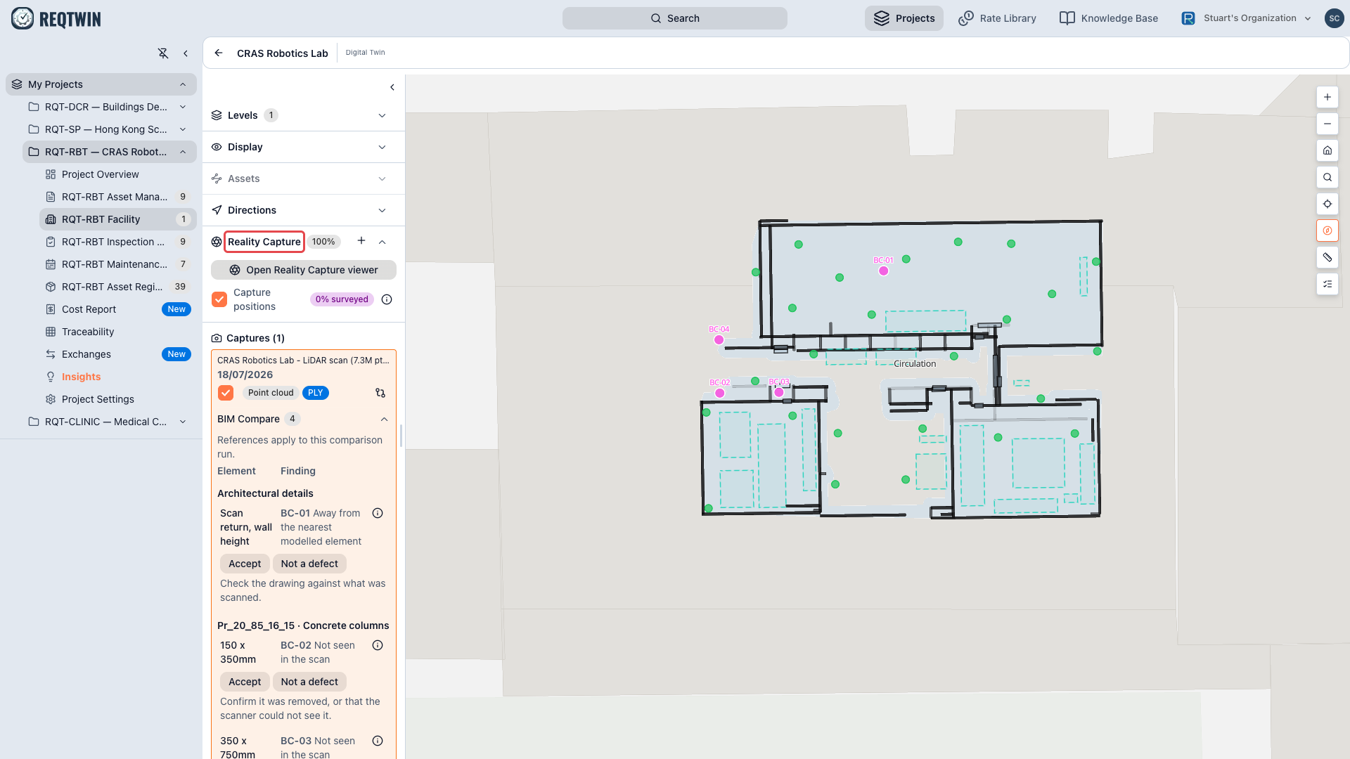
The Reality Capture section, boxed in red, sitting in the map's left panel below Levels, Display, Assets and Directions.
Opening a capture
Expand the section and you get the facility's captures, newest first, each with its date and a badge for its kind and provider. The date sits with the name because a scan from two years ago and one from last week are different objects.
Click the card to open it in the viewer beside the plan.
| On the card | What it does |
|---|---|
| Run BIM Compare | Measures this scan against the model. See "Comparing a Scan Against the Model" |
| Open pano tour externally | Opens a panorama capture at the provider |
Capture positions
Capture positions draws the stations on the plan. Hover one to preview it, click to step inside it.
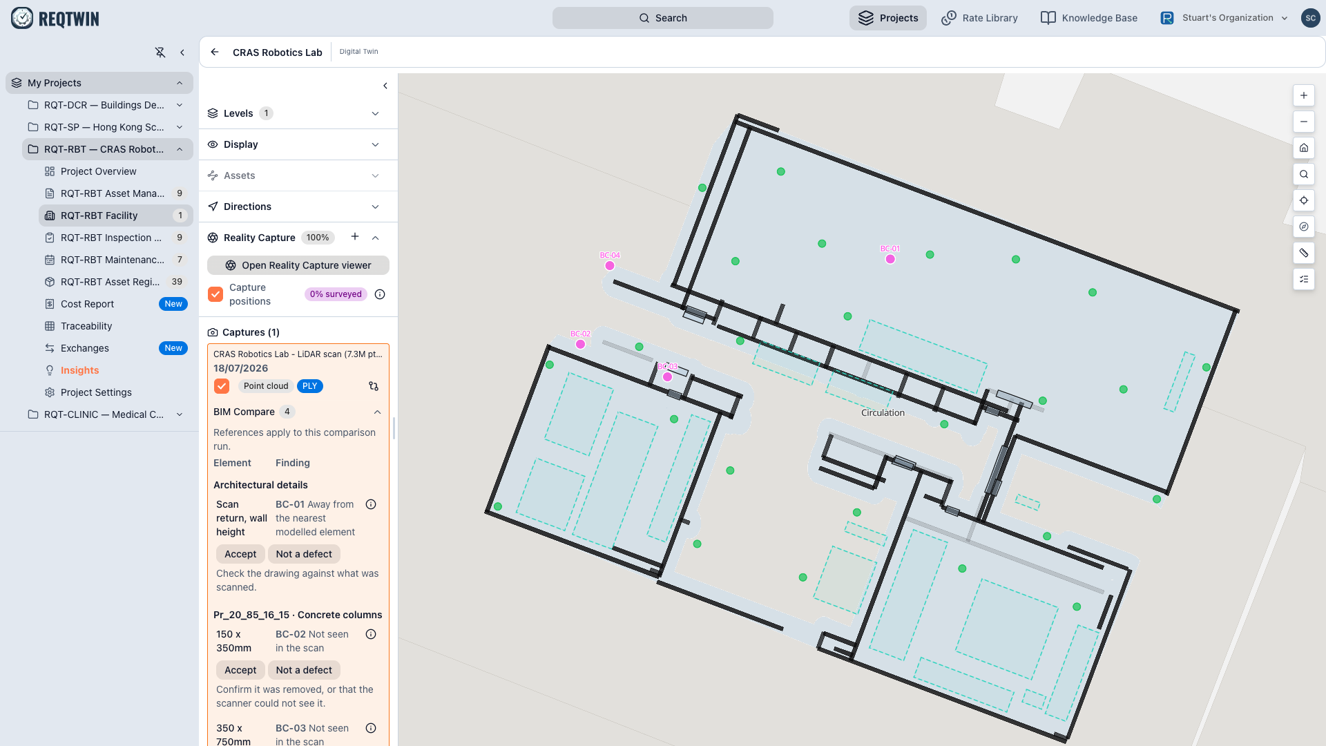
Capture positions drawn on the floorplan, each a station the surveyor stood at.
Beside the toggle is a badge saying what share of those positions were surveyed rather than computed from the capture. A reading of 0% is not a fault: a raw LiDAR scan carries no station poses, so every position was derived. The capture is real either way, and a derived position is still a position worth standing at.
The two percentages in this section answer different questions and are kept apart deliberately. The heading says how much of the building the scan reaches. This badge says how the positions behind that reach were arrived at.
Point-cloud slice
A slice is a flat cut through the cloud, pre-rendered and drawn under the plan. There are two bands, and they are meant to be read together.
| Band | What it draws |
|---|---|
| Wall band | The fabric: where the building's surfaces actually stand |
| Asset band | What is standing inside it |
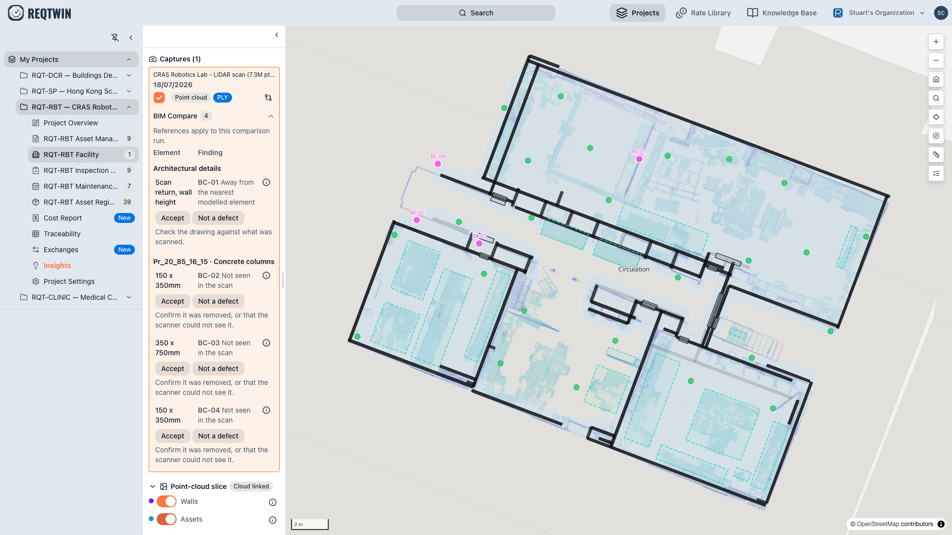
The two slice bands switched on, cut from the point cloud and drawn under the plan, each with its own colour swatch on its own control.
Each switch carries its own colour swatch, so the legend is the control, and its own i giving that band's extent. The heading badge reads Cloud linked or No cloud file, which matters before you toggle anything: the bands can switch on while the cloud they were cut from is unlinked, and the viewer would open to nothing.
Band extents are reported, not adjustable. They came from occupancy measurements rather than a thickness preference. A wall band reaching higher fills the corridor solid, and an asset band reaching the same height stops being an asset band.
Inside the viewer
The viewer docks beside the plan and puts you at a capture position, looking out. Stepping between stations is a short eased move rather than a jump, and the plan draws a cone showing where you are aimed, so both panes read as one place.
Measure in 3D measures between two points in the cloud. Click two points, keep clicking to run a chain, and the distance appears beside the button and over the canvas. It reports slope distance, the true straight-line separation including height. The plan's own Measure reports the horizontal span instead. Which you want depends on what you are measuring.
Colour carries one meaning each, in both panes:
| Colour | Meaning |
|---|---|
| Orange | A measurement |
| Green | A capture position |
| Teal | An asset |
| Pale blue | A room |
| Magenta | A BIM Compare finding |
Two controls that live in Display instead
Both filter the whole map, so they must stay reachable on a facility with no capture at all.
Source switches between IFC, the authored model, and Generated, what ReqTwin derived from the scan. The authored model is never deleted either way.
Scan-derived assets (unverified) draws equipment extracted from a cloud and not yet reviewed, teal and dashed so it never reads as authored fabric.
Known limits
Scan-derived assets are unverified until reviewed, which is why they stay out of the Assets panel.
Georeferencing is per capture. One without it opens in the viewer but places no marker on the plan.
Captures are attached from the + on this section's heading, not from the document-upload dialog.
Nothing here writes geometry into the model. BIM Compare reports; a person decides.