Knowledge Base
Drawing to a Standard
The sheet is a sheet
Most drawings sit inside a framed sheet with alphanumeric grid zones down the sides, the way ISO 5457 describes one. The zones are not decoration: they are what lets a reviewer say "the isolator at C4".
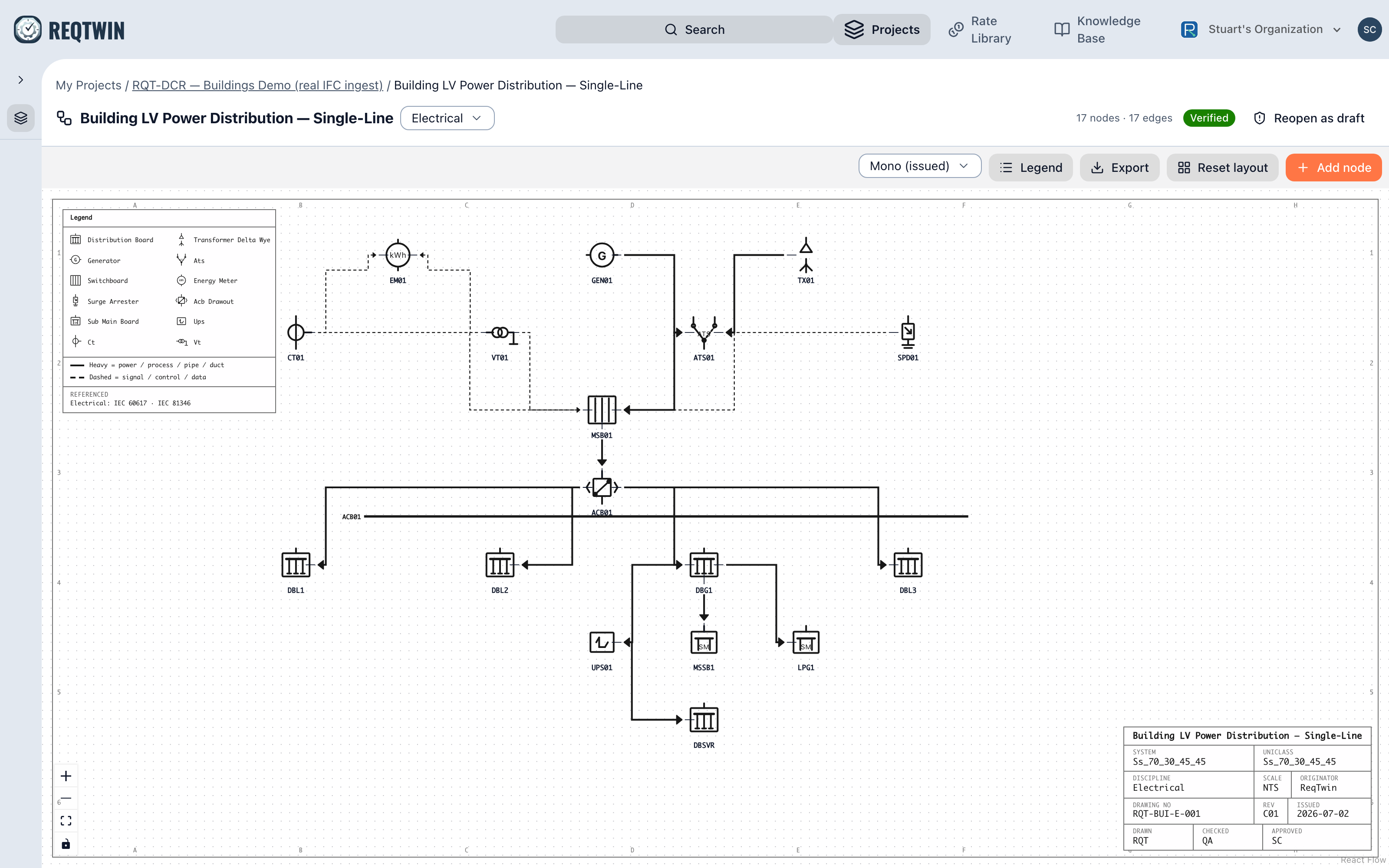
An electrical single line inside its frame: grid zones around the border, legend top-left, title block bottom-right.
The sheet is drawn at A3 landscape proportions, letterboxed in the pane, so what you see is the shape of the paper. It used to take the shape of the window, which meant a drawing was laid out against one shape and read against another: measured, a sheet appeared to fill 53% of its width while filling 82% of an A3-shaped frame.
The drawing area is the sheet minus its furniture. The legend occupies the top-left and the title block the bottom-right identification zone, and the drawing is fitted into what is left, so content never runs under either.
Not every drawing type is an ISO sheet
A railway signalling plan is not. Published signalling plans carry no drawing frame and no grid zones; the track fills the sheet, with a centred title, a short note block and a single issue strip. Wrapping one in drafting-office furniture is not a stricter standard, it is the wrong standard, and the furniture takes the room the track needs.
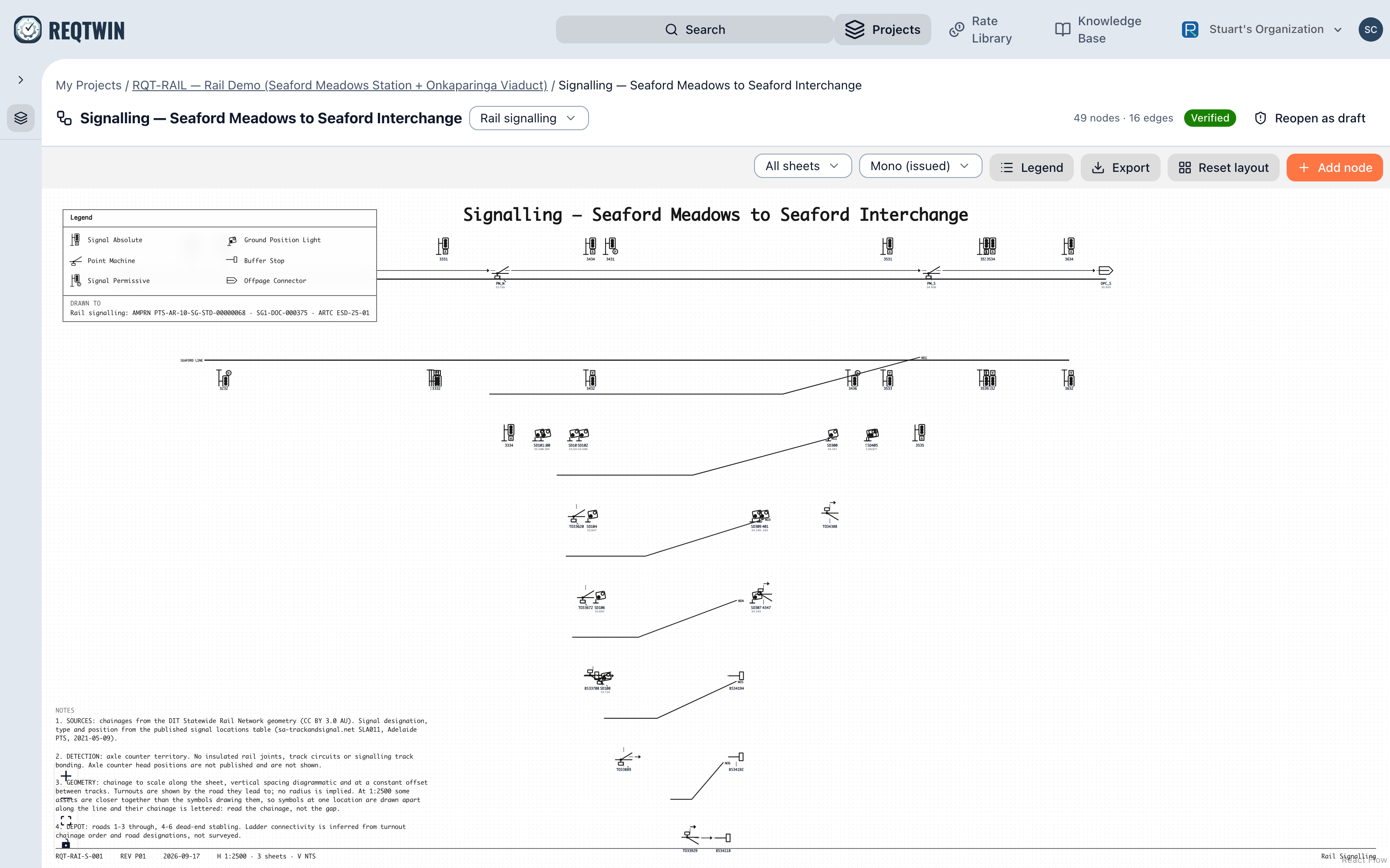
A signalling plan: running lines across the sheet with the depot roads converging into them.
The title block
The bottom-right identification zone carries an ISO 7200 title block: title, system, Uniclass classification, discipline, scale, originator, drawing number, revision, issue date, and the drawn, checked and approved boxes. An unissued field prints as an explicit dash rather than collapsing the row, a blank Checked or Approved box is the signal that a drawing is not cleared, where a missing box just looks like a different title block.
Scale is computed, not asserted
Where a drawing plots to scale, the sheet states the scale it actually holds, worked out from the span it covers against the drawing area, snapped to a value the governing standard permits. Where no permitted scale fits the sheet, it says how many sheets the drawing needs rather than quoting one that would not be accepted.
A railway signalling plan on the Adelaide network reads H 1:2500 · 3 sheets · V NTS. 1:1000 and 1:2500 are the scales AMPRN permits, the route needs three of them, and the vertical is not to scale because the offset between tracks is a drawing convention rather than a distance. A title block that claims a scale the layout does not hold invites a reader to measure off a drawing that cannot be measured.
The legend is derived, not written
The legend lists the symbols actually on the sheet, every time. A key listing symbols the drawing does not use is noise; one omitting a symbol it does use is a defect. Neither is possible here.
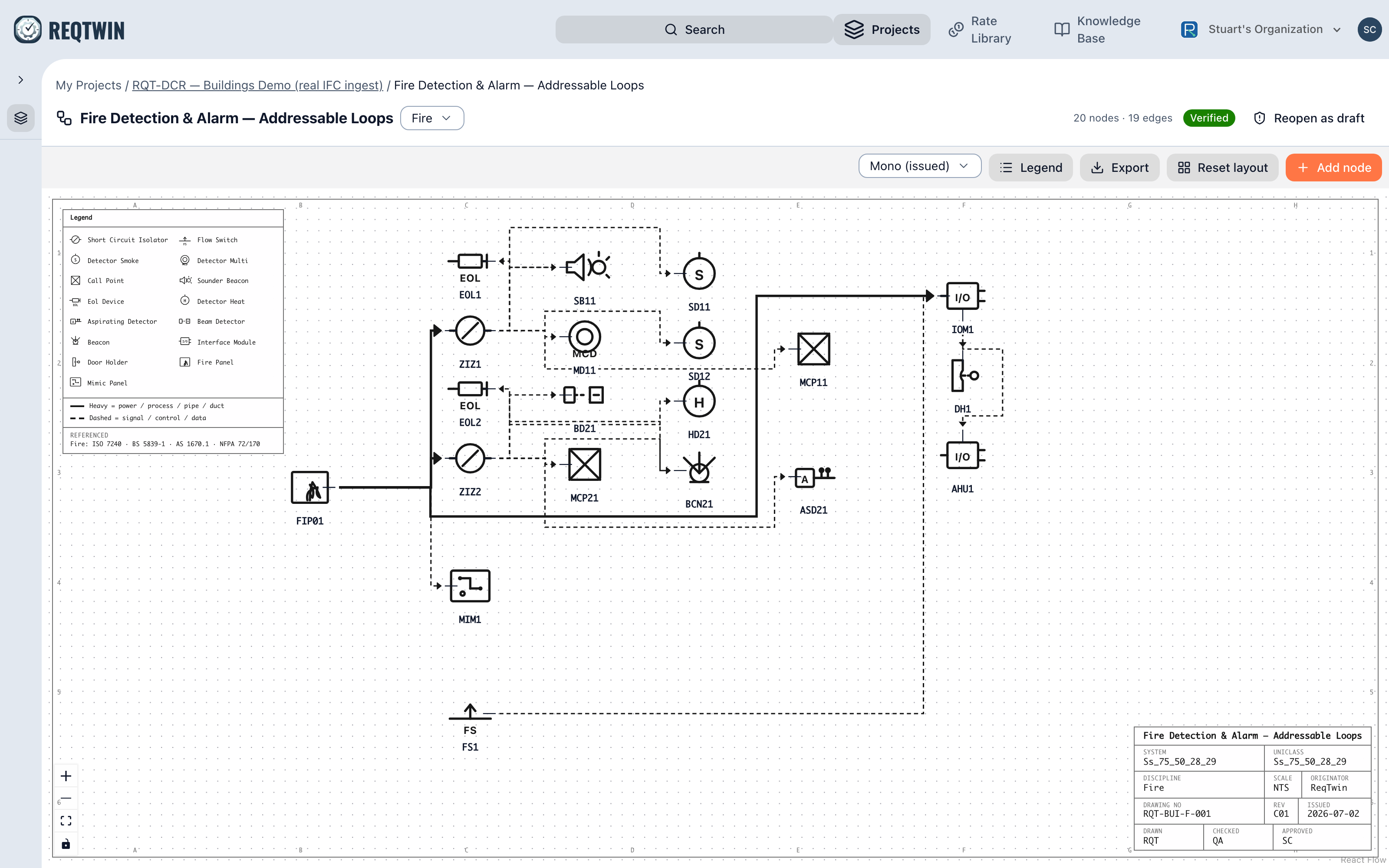
The fire alarm legend: only the symbols on this sheet, the line conventions, and the standards the sheet is drawn to.
Drawn to, and referenced
The last rows of the legend state what the sheet was drawn to. They separate two different claims, and the difference is visible to a reviewer:
Drawn to: the standard was obtained and read, and the symbols are drawn from it.
Referenced: the standard governs the drawing but has not been obtained.
Most engineering standards are sold rather than published, so for several disciplines the honest claim is the second one. The rail sheet is the exception: AMPRN publishes its signalling principles, so its signals are drawn from the network's own standard. An Absolute signal carries a square "A" plate vertically below the head, a Permissive signal a round "P" plate diagonally below, and a ground shunt signal is a position light. A drawing that asserted conformance to a document nobody had opened would be making a claim it cannot support.
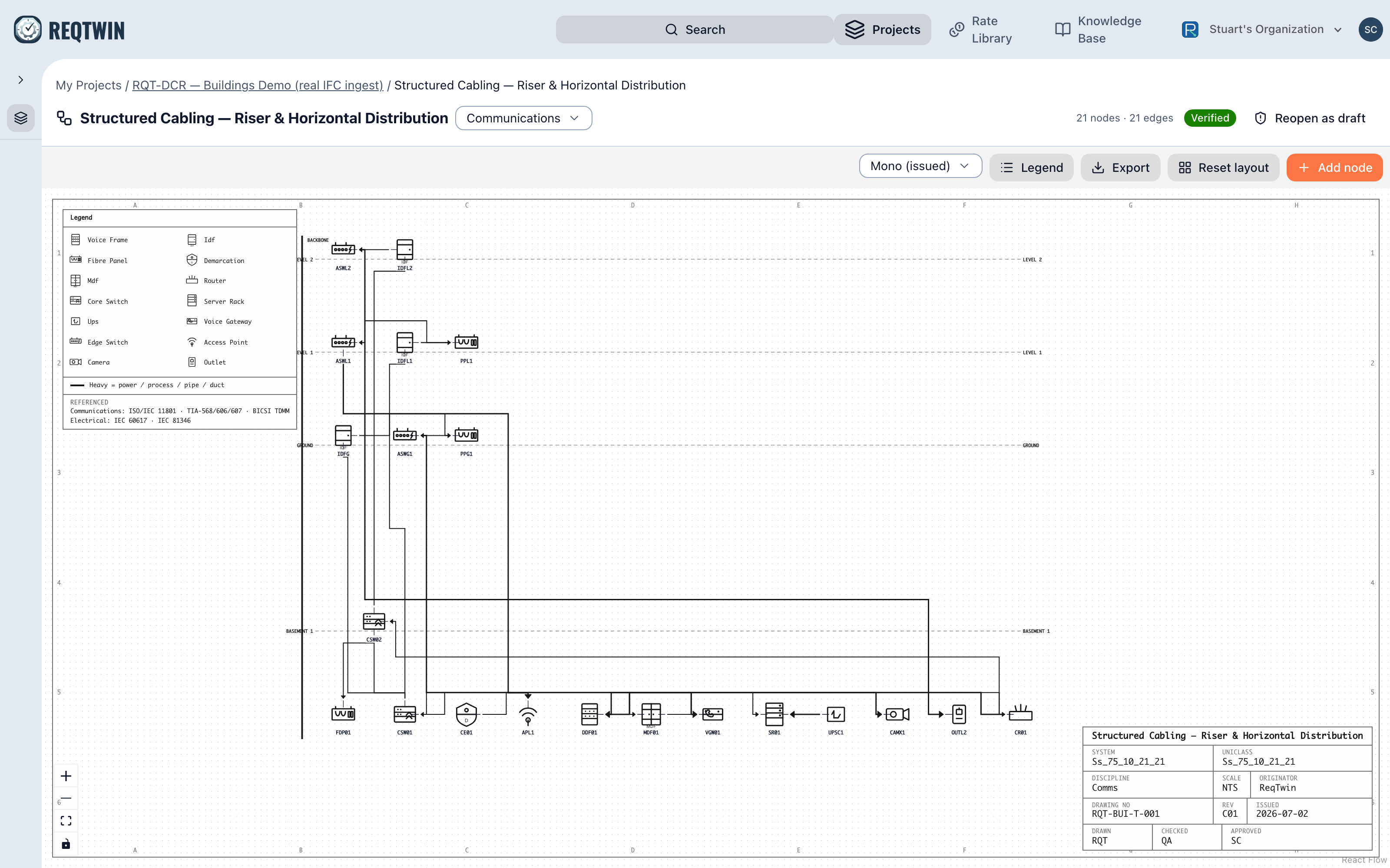
A structured cabling riser, with the communications standards stated on the sheet.
Lettering
Text heights follow the governing standard where it sets them. A signalling plan letters its title at 5 mm, track names at 2.5 mm and everything else at 1.75 mm, which at A3 is what keeps a dense sheet readable without oversizing the detail.
Mono for issue, colour for screen
The sheet has two ink modes. Mono (issued) is the default and is what a drawing is issued as: one ink, line weight carrying the meaning. Colour is a screen convenience that tints symbols by discipline, useful while you work and wrong on an issued sheet. That holds for signalling too, colour on a signalling drawing encodes drawing status, and every layer plots black.
Printing
Print plots the sheet alone, on A3 landscape with an 8 mm margin, without the application chrome. Cmd+P does the same thing.
A plotted sheet carries more than the screen does, because the screen has the application around it and paper has nothing. The legend and the general notes collapse to chips in the corners while you work, so they do not cover the drawing, and both open for the plot. The title block appears only on the plot, for the same reason: on screen the drawing number, revision and scale are already in the page header above the canvas.
The scale in the title block is measured off the sheet in front of you, not a figure typed against the drawing. It is taken from the chainage span actually rendered and the fraction of the sheet width it occupies, then reported at the nearest scale the drawing's own standard permits, which is why it says "nominal".
Only the horizontal carries chainage on these sheets, so the vertical is called out separately as NTS: the offset between two tracks, or the spacing of devices up a strip, is a drawing convention and not a distance. A sheet that cannot be measured at all states NTS outright.
The permitted scales are the discipline's. A railway plan may be issued at 1:2500, or 1:1000 for clarity, and nothing between them, so a measured 1:1600 is reported as the permitted scale it is closest to rather than as a true ratio no standard allows. Everything else uses the ISO 5455 preferred scales. The nearest is found multiplicatively, because the midpoint between 1:1000 and 1:2500 is 1:1581, not 1:1750.
Choosing what goes on the paper
Print area draws an orange box on the sheet. Drag it over the part of the drawing you want plotted and press Plot this area, and the sheet re-frames to it.
The box is held to A3 landscape whatever you drag, because a window of any other shape cannot be plotted without distorting or padding it. The orange box is a screen mark and is never plotted: on an issued sheet it would read as a revision cloud.
Because the sheet re-frames rather than storing a region to crop at print time, the scale in the title block follows the window on its own - it is measured off the sheet, and the sheet is now the window. Whole sheet puts the whole drawing back.
Everything on the sheet is lettered at or above the 2.5 mm minimum character height ISO 3098 sets for A3.
Related
Schematic Drawings covers the disciplines and how each is laid out.
Verifying a Drawing covers what is checked before a drawing is marked verified.
Revisions and What Changed covers issuing a drawing and reading what moved since the last issue.