Knowledge Base
Schematic Drawings
A drawing, not a diagram
A Schematic document is a drawing in the sense a design office means it: symbols drawn to a standard, connectors that route around what they pass, a framed sheet with a title block, and a legend derived from what is actually on the page. It sits in the project alongside the Requirements register, the ITP, the Programme and the BOM, and it is reached the same way.
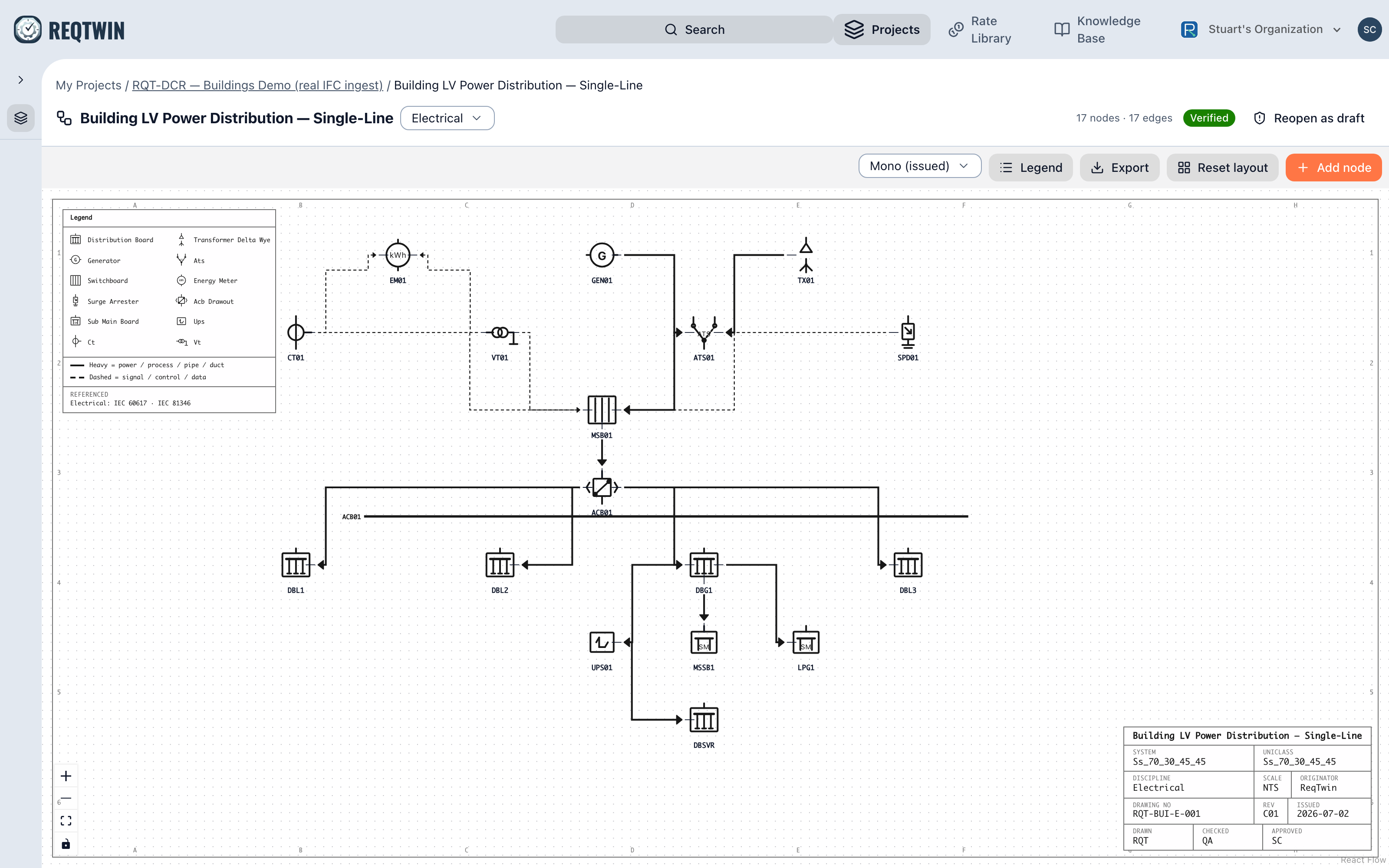
An electrical single line: the busbar runs across the sheet with distribution boards combed off it, metering and protection tapped above.
The example above is an LV single line. The busbar is drawn as a single heavy run with the boards hanging off it, which is the one thing that makes a single line read as a single line rather than as a tree of boxes. A switchboard section is a busbar, and drawing it as a box is the most common way a generated single line stops looking like one.
The drawing knows its discipline
Pick a discipline and the drawing lays itself out the way that discipline is drawn. The same graph of symbols and connections produces a different sheet depending on whether it is electrical, fire, mechanical, communications or rail, because those trades do not draw the same shapes.
A fire alarm system is drawn as a loop. Detectors, call points and sounders sit around an addressable circuit that leaves the panel and returns to it, with the end-of-line devices and loop isolators in their places.
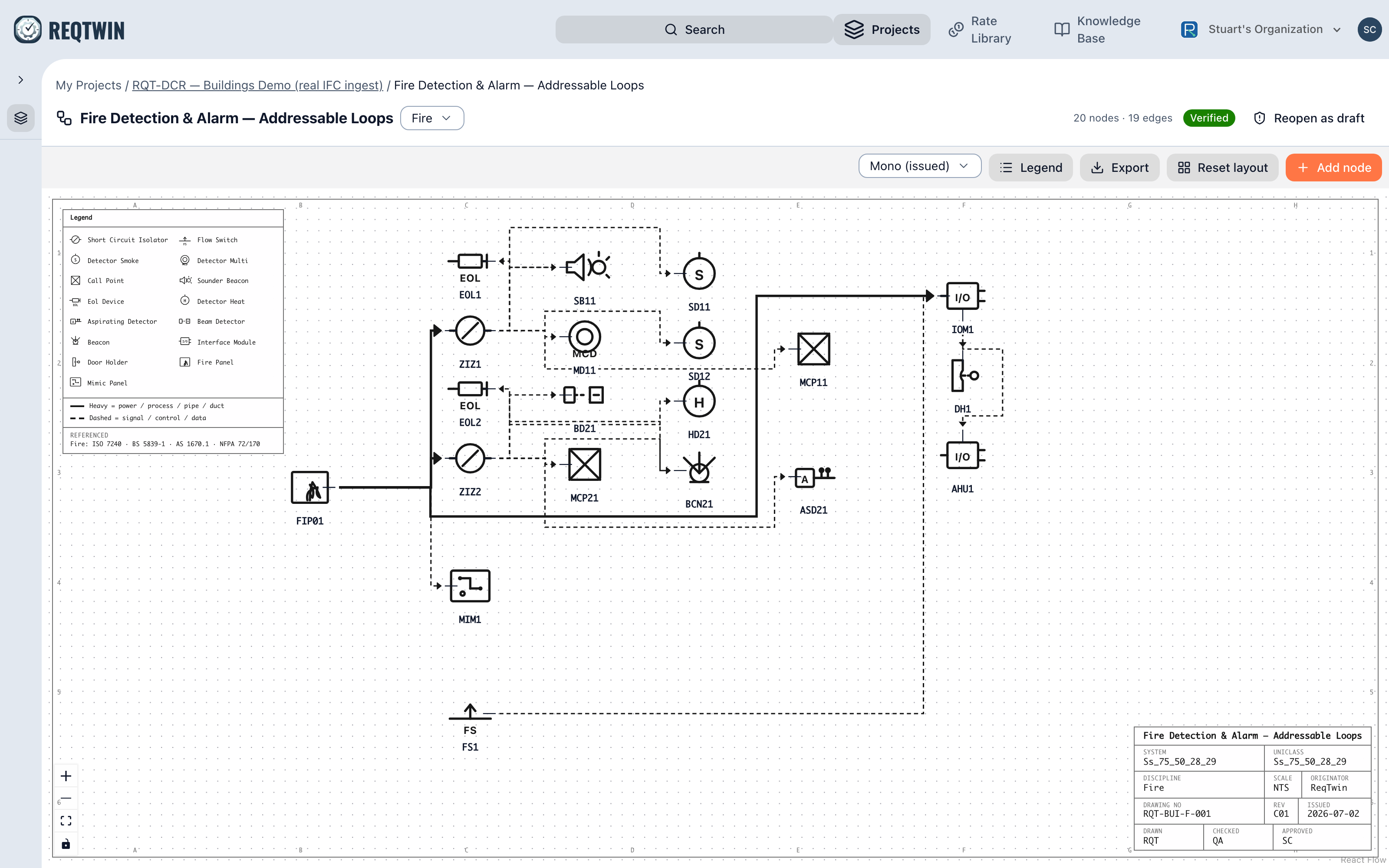
A fire detection and alarm drawing: addressable loops leaving the indicator panel, with detectors, call points, sounders and end-of-line devices.
An air handling unit is drawn as a cased train: the components inside the casing abut in sequence inside a bordered enclosure, with supply and return banded above and below.
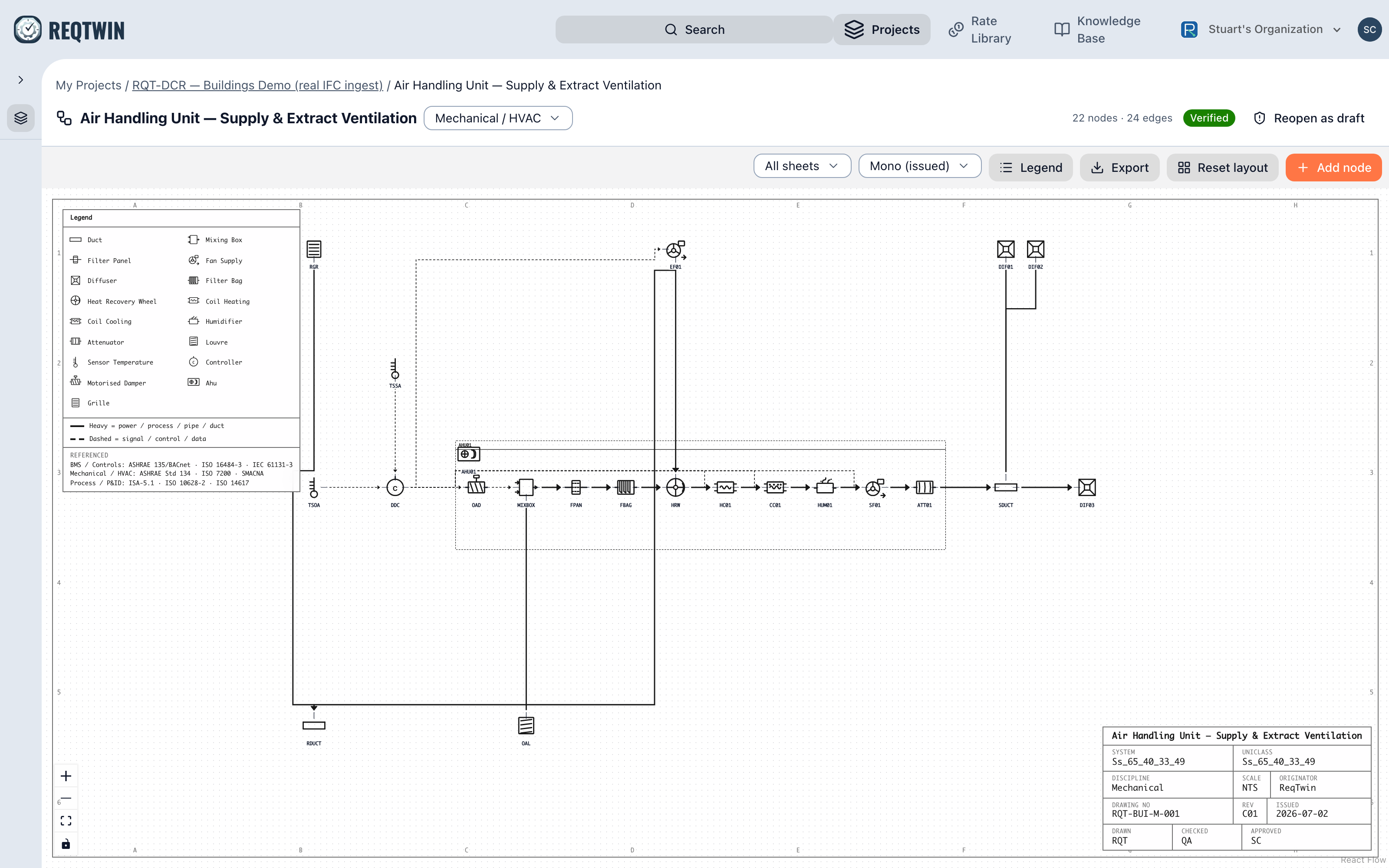
An air handling unit drawn as a cased train: dampers, filters, coils, heat recovery, fan and attenuator in sequence inside the casing.
Structured cabling is drawn as a riser. Security is drawn as a camera run. Process and instrumentation is drawn as an inline flowsheet with the instrument bubbles floating above their tapping points.
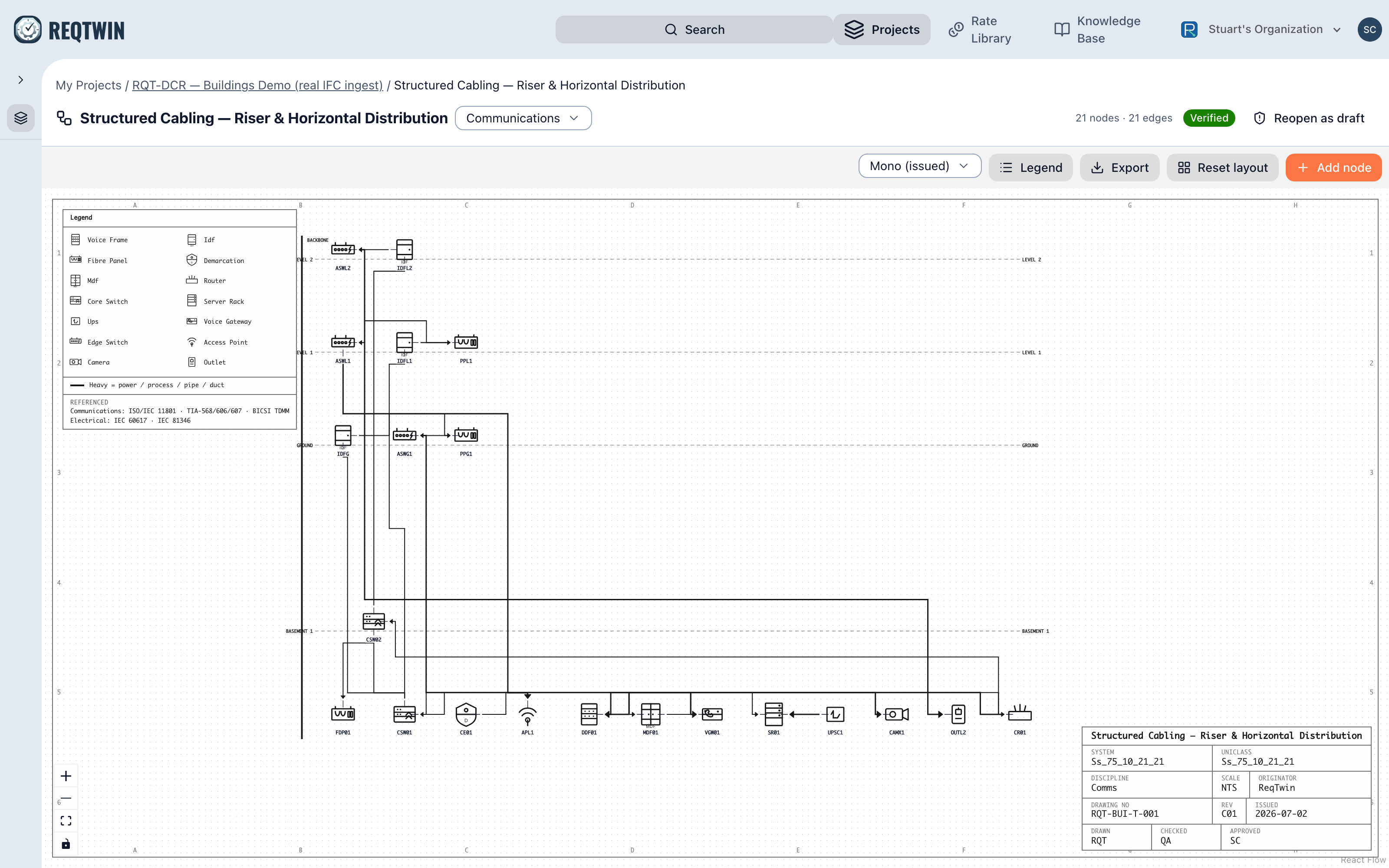
A structured cabling riser: distribution frames banded by storey, with dashed floor datums across the sheet.
A riser draws no backbone line of its own. Where a backbone exists it is an asset on the drawing with connections of its own, and a second heavy line drawn beside it would assert a cable the data does not have. The dashed floor datums are drawing furniture, not conductors, and they are what make the stack read as a building.
Tags, not database keys
A symbol carries the designation a drawing carries, not the identifier the database uses. Assets arriving from an IFC ingest bring their provenance with them, so a detector might be stored as ex_fire_sd11; on the sheet it is SD11, and an air handling unit's train reads OAD · FPAN · FBAG · HRW · HC01 · CC01 · HUM01 · SF01.
The prefix removed is whatever every tag on that sheet shares, because a prefix common to the whole drawing carries no information on it. The stored identifier is untouched, so the inspector, the schedule and every cross-reference still resolve.
Above a dozen symbols the sheet carries tags alone and the descriptions move to the hover and the inspector. That is the CAD norm, and it is also the difference between a drawing and a smear: descriptions collide diagonally, strike through connectors and overhang the legend in a way that tags do not.
Connectors route, they do not just connect
A connector finds its way around the symbols in its path rather than through them, and arrives head-on at the symbol it points to. A line that crosses a symbol body reads as a connection that is not there, and an arrow arriving side-on leaves which symbol it serves ambiguous. Text is masked out of the linework, so a connector passing behind a tag stops at the text and resumes after it.
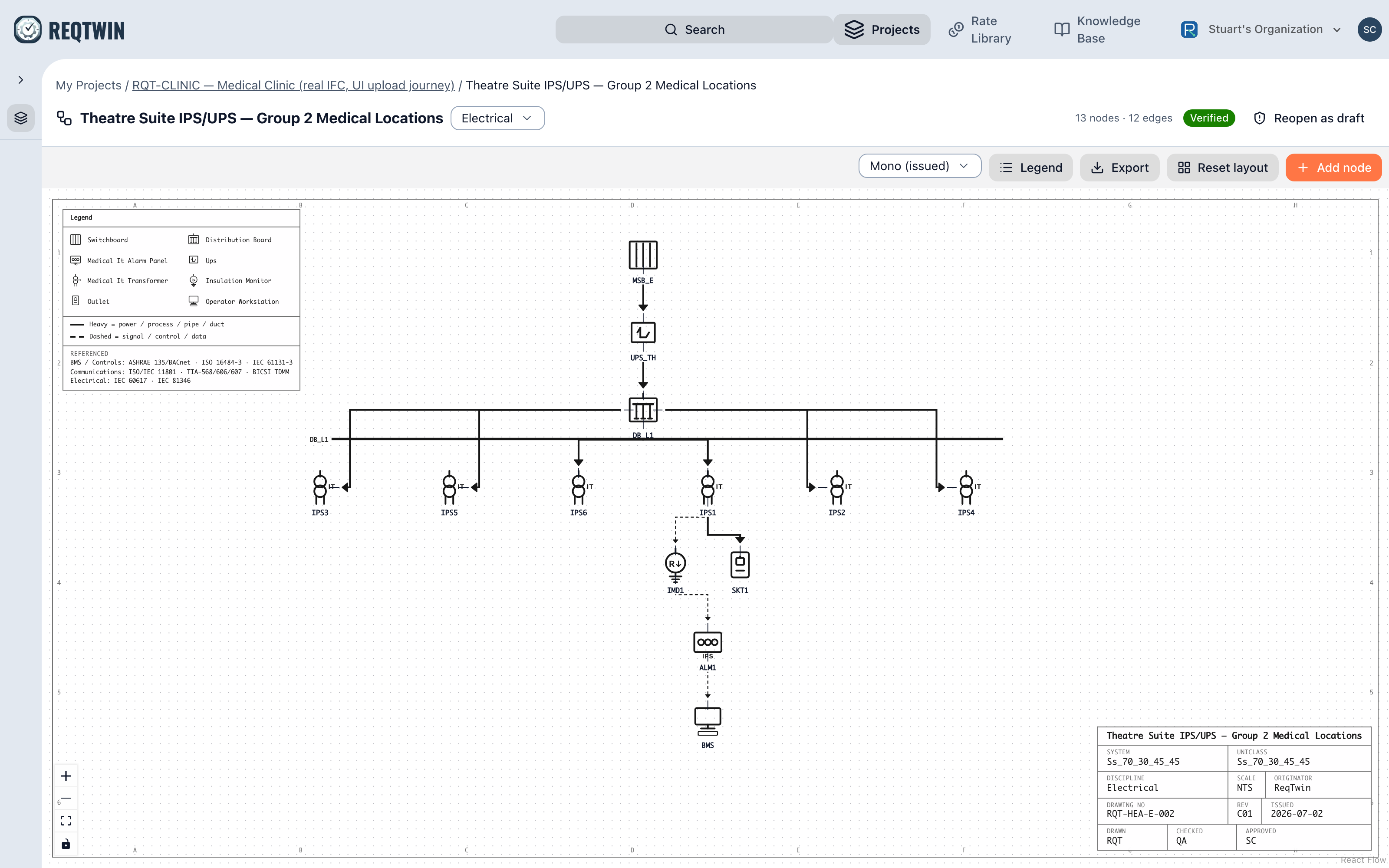
A medical IPS and UPS single line for group 2 locations, with the isolating transformer, insulation monitor and alarm panel.
Where a drawing comes from
You can draw one by hand with Add node, choosing from the symbol library by picture rather than by typing a key. A drawing can also arrive from a DXF or a vector PDF, or be generated from the project's own asset data.
Whichever way it arrives, the drawing is rows in the project database, not a file. The symbols on it are the same assets the BOM and the Digital Twin know about, so a drawing cannot drift from the project the way a DWG in a folder does, and where the project holds real geometry the drawing can be built from it rather than from a description of it.
Undo and redo
Undo reverses your last change to the drawing and Redo puts it back. Ctrl+Z and Ctrl+Shift+Z do the same. It covers adding, deleting, renaming, retyping, moving a symbol, and the same for connectors.
Three things are worth knowing about how it behaves, because they are deliberate.
It undoes one action, not one row. Reset layout repositions every symbol on the sheet, and that is one action, so one undo puts all of them back. Deleting a symbol takes its connectors with it, and the undo brings the symbol and its connectors back together - a half-restored symbol with no connectors would be a drawing nobody authored.
It undoes your own work. On a drawing two people can edit, undo walks back your own changes and steps over theirs. Reversing whatever happened to be last would let one person silently undo a colleague's change, and on a shared sheet that is how work goes missing.
It is recorded, not remembered. The change log lives with the drawing rather than in the browser, so undo and redo still work after a reload, and the log is written by the database itself rather than by the screen you made the change on.
Drawing something new retires the redo. Undo a deletion, then draw something else, and the deletion can no longer be redone: putting it back would reach past the work that came after it. The undo itself is unaffected - you can keep stepping back through your own changes.
A reader with view-only access cannot undo or redo, for the same reason they cannot edit.
Related
Drawing to a Standard covers the sheet frame, the title block, scale and the basis of preparation.
Verifying a Drawing covers the draft and verified states and what is checked.